You specified HF cards, the integrator installed the readers, and now the credentials only read when they are almost touching the antenna. At 2 cm, a “contactless” card behaves like a wired one — and the rollout slips. The good news: a 2 cm read range is almost never a defective card. It is a system-design gap you can spec out of the program before a single box ships.
What Actually Limits RFID Read Range

Most 13.56 MHz cards your program will use — MIFARE, NTAG, DESFire, ICODE and their equivalents — are near-field, inductively coupled devices. The reader’s coil creates a magnetic field; the card’s antenna picks up energy and talks back by loading that field. There is no “radio wave” travelling through the air the way a Wi-Fi packet does. Read range is governed by mutual inductance between the two coils, which depends on antenna area, coil geometry, the resonant Q factor, and the reader’s field strength.
Here is the part buyers miss: at 13.56 MHz the field is magnetic, and in the near field its strength falls off roughly with the cube of distance (≈1/d³). Move the card from 2 cm to 4 cm and you have already cut the available coupling by roughly eight times. That steep fall-off is why a “2 cm” card rarely becomes a “10 cm” card just by swapping readers — the physics fights you. It also explains why HF (centimetres to about a metre) and UHF (several metres, radiative far-field) are different tools; if you need metres, you are in the wrong frequency band. Our LF vs HF vs UHF frequency guide walks through that choice.
Card Antenna Size and Where It Sits

Inside every contactless card is an inlay — a thin etched copper or aluminium loop. Its inductance, and therefore its read range, scales with the loop’s enclosed area. A small or partial antenna (common in very thin cards or in dual-interface products that must also fit a contact module) simply cannot capture as much field as a full-size loop.
Position matters as much as size. A card with a small or off-centre antenna can read at barely half the distance of an identical card with a full-size, centred loop — on the exact same reader. Edge-mounted antennas, antenna “windows” left clear for a signature strip, or inlays squeezed to one corner all quietly cost you range. When you brief a supplier, ask for the inlay’s antenna dimensions and enclosed loop area and put a minimum in the specification; do not accept an arbitrarily miniaturised antenna for a program that needs distance. See how smart cards are made for where the inlay sits in the stack.
Reader Power, Antenna, and Gain

It is tempting to blame the card and ask for a “stronger reader.” Reader output is not unlimited. In Europe, 13.56 MHz equipment must stay within ETSI EN 300 330 field-strength limits (etsi.org); in the United States the relevant ceiling is under FCC Part 15, §15.225 for the 13.110–14.010 MHz band (eCFR).
Regulatory field-strength caps mean a “stronger reader” only helps up to the legal ceiling — beyond that, antenna geometry is the only lever. Within the limit, a larger reader coil, more turns, and correct placement do help; so does matching the reader coil’s orientation to the card. The practical takeaway for buyers: specify the reader coil size and required free-air read distance together, and verify both against the regulation rather than trusting a vendor’s “long-range” marketing claim.
ISO 14443 vs ISO 15693 — What Ranges to Expect
Both dominant HF standards run at 13.56 MHz, but they are designed for different distances. ISO/IEC 14443 is the “proximity” standard behind payment, access, and most ID cards — engineered for a tap, typically reliable at 0–4 cm and stretching to about 10 cm only in favourable conditions (iso.org/14443). ISO/IEC 15693 is the “vicinity” standard, running at a lower data rate so it can reach up to about a metre — commonly 10–70 cm in the field (iso.org/15693).
| Standard | Coupling / mode | Typical read range | Best fit |
|---|---|---|---|
| ISO/IEC 14443 | Proximity (tap) | 0–10 cm (reliable 0–4 cm) | Payment, access, ID — tap-and-go |
| ISO/IEC 15693 | Vicinity (long HF) | 10–100 cm | Asset tracking, library, logistics gates |
If your program needs reads beyond roughly 10 cm at HF, specify ISO 15693 — not 14443. 14443 is purpose-built for a tap; pushing it past its design envelope is exactly how you end up at 2 cm. Chip choice also interacts here, which is why our MIFARE vs NTAG vs ICODE comparison matters at procurement time.
Metal, Liquid, and Other Materials That Kill Your Range
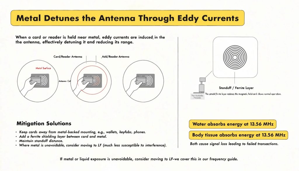
Two materials sabotage 13.56 MHz more than any other. Metal induces eddy currents in the card or reader antenna and detunes it, collapsing range. Water and body tissue absorb energy at 13.56 MHz. The result is the classic field complaint: a card that reads at 5 cm in free air drops below 1 cm when held against a metal door frame, a phone, or a wallet with a metal plate.
A card that reads at 5 cm in free air can fall under 1 cm against a metal surface or a body — the material, not the card, is the culprit. Mitigations buyers can specify: keep cards off metal-backed mounting, add a ferrite shielding layer between card and metal, maintain a standoff distance, and, where metal or liquid is unavoidable, consider moving the program to LF (which tolerates metal and liquid far better) — covered in our frequency guide.
Card Orientation and How Your Readers Are Mounted

Coupling is strongest when the two antenna planes are parallel. Present the card edge-on — antenna perpendicular to the reader coil — and reads degrade or vanish. Reader mounting shapes the field too: a wall reader, a turnstile pole, and a desktop pad each produce a different field volume, and a card that sails through on the bench can fail at the real doorway.
The single most common “2 cm” complaint is simply a card presented at the wrong angle to a wall-mounted reader — rotating it 90° often restores a 5–10 cm read. Buyers should define a “presentation envelope” in the specification and pilot at the actual doorway with real cards and real wallets, not on a lab bench.
A Pre-Specification Tuning Checklist for Buyers

You do not fix a 2 cm problem after installation — you design it out in the specification. Use this checklist when you brief a supplier or run a pilot:
- Define the required read distance per touchpoint. Gate, turnstile, and handheld each need their own number — do not specify one blanket range.
- Choose the standard up front. 14443 for tap, 15693 for longer HF range, UHF only if you truly need metres.
- Request antenna dimensions, loop area, and Q factor from the supplier and write minimums into the RFQ. Our RFQ specification template has the slot.
- Require an on-site read-range test report from samples — in free air and in your worst-case mounting — before bulk.
- Ban metal-backed mounting and specify ferrite shielding where metal is unavoidable.
- Pilot at the real doorway with real cards and real wallets, not on a bench.
- Keep a sample kit for incoming acceptance testing. Start with requesting card samples before your order.
Frequently asked questions
- Can I just buy a more powerful reader to fix 2 cm? Only up to the legal field-strength ceiling (ETSI EN 300 330 / FCC Part 15). Past that, antenna geometry and standard choice are what move the needle.
- Why does the same card read fine on one door and fail on another? Usually reader mounting, orientation of presentation, or nearby metal/liquid — not the card. Pilot at the real location.
- Is UHF the answer if HF cannot reach? Only if you need metres and can tolerate UHF’s different cost, privacy, and collision behaviour. For most ID programs, switching HF 14443 to 15693 solves it first.