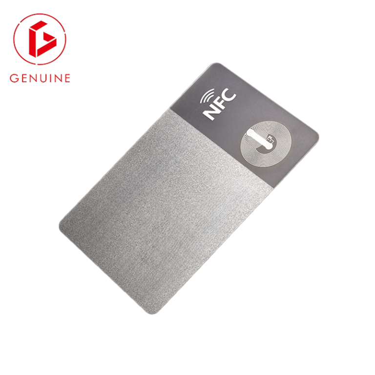
You run a mixed reality. The staff entrance still reads 125 kHz prox fobs from a system installed years ago. The new office doors expect 13.56 MHz smartcards with mutual authentication. And the warehouse wants to scan badges from across a dock door at UHF. Three reader populations, three credential types — unless you collapse them onto a single card. A dual-frequency card embeds two independent RFID inlays in one badge, so one credential speaks two (or more) protocols. This guide walks RFID integrators and procurement leads through what dual-frequency cards are, where they actually pay off, the antenna and read-range trade-offs you must design around, and how to specify one with your manufacturer so the sample you approve is the card you receive in bulk.
What a dual-frequency card actually is (and when you need one)
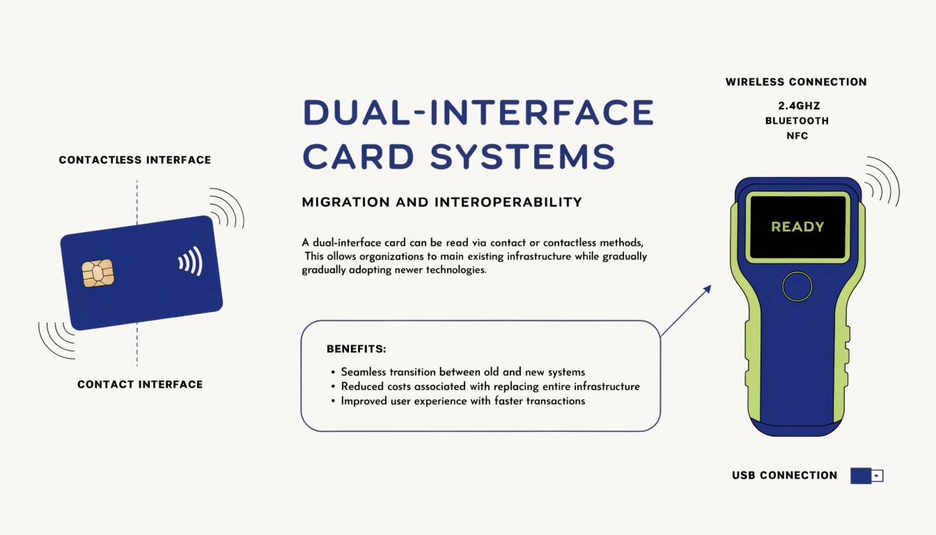
A dual-frequency card is a standard CR80 card body (per ISO/IEC 7810) that carries two separate RFID inlays — each with its own chip and antenna tuned to a different frequency. The two common pairings are LF (125 kHz) + HF (13.56 MHz), and HF (13.56 MHz) + UHF (860–960 MHz). This is not the same as a dual-interface card: a dual-interface smart card uses one chip with two antenna ports on the same frequency family, whereas a dual-frequency card is genuinely two chips. You need a dual-frequency card when no single protocol covers your whole environment — most often during a technology migration, or when one card must serve both secure access and long-range logistics. If you want the frequency fundamentals first, start with our LF vs HF vs UHF RFID frequency guide.
LF + HF: pairing 125 kHz proximity with 13.56 MHz smartcard
Low-frequency 125 kHz is the workhorse of legacy access — EM4100 and HID Prox fobs that read through wallets and near metal. High-frequency 13.56 MHz (ISO/IEC 14443, and ISO/IEC 15693 for vicinity cards) carries the crypto-capable credentials: MIFARE, DESFire, or your own applets. The pairing lets you keep the old 125 kHz readers running while you roll out cryptographically secure 13.56 MHz credentials — no rip-and-replace of door hardware. Staff carry one badge; the legacy turnstile still works on LF while the new secured doors authenticate on HF. When choosing the HF chip, our MIFARE vs NTAG vs ICODE comparison helps you match memory and security to the use case.
HF + UHF: access control plus asset and logistics tracking
Here the same card does double duty as a personnel badge and a tracked asset. HF handles door and PC login at short range; UHF (ISO/IEC 18000-6C / EPC Gen2, standardized by GS1) reads at several meters. UHF read ranges of several meters let the same card be read across a dock door or gate without being pulled from a wallet. A factory can therefore use one badge for both staff access (HF) and tool or vehicle tracking at the yard (UHF). Note the trade: UHF is a far-field technology that metal and water detune far more than LF or HF, so placement and the surrounding environment matter.
How two antennas coexist inside one card (layout and materials)
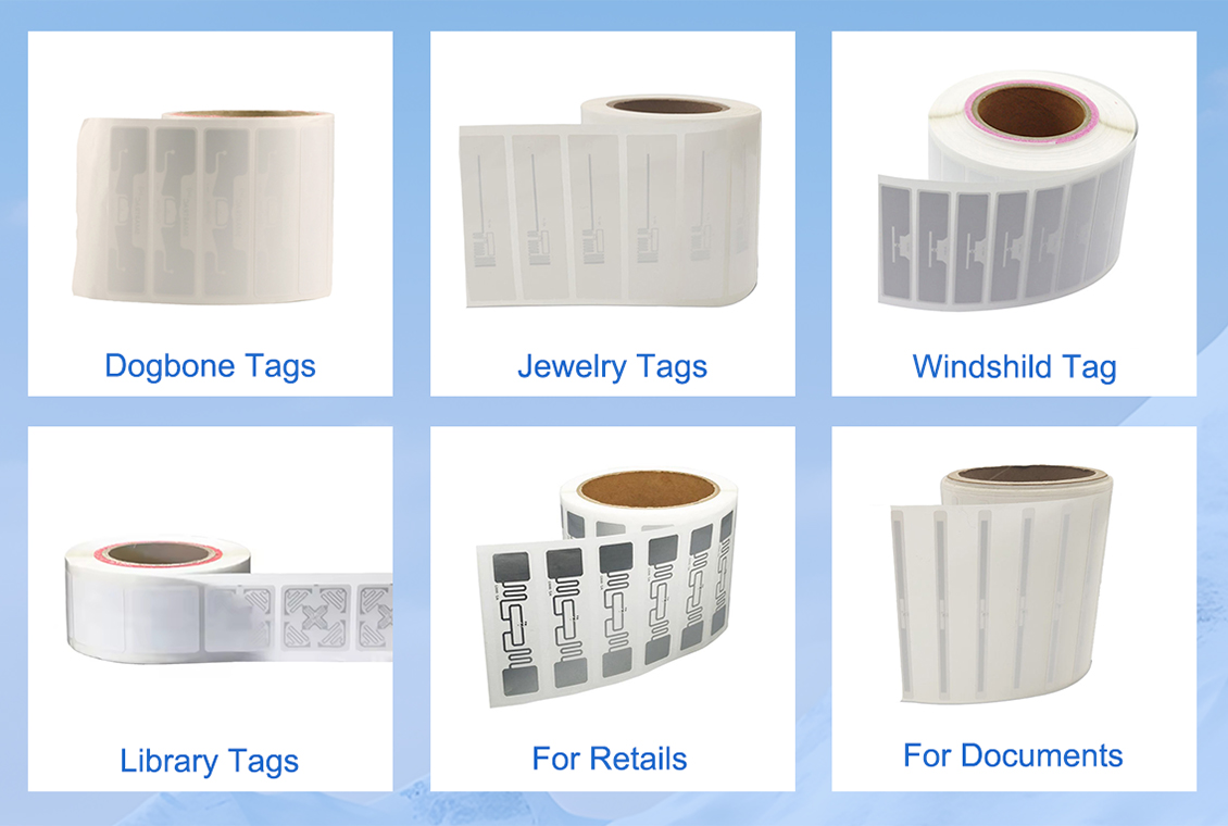
This is where manufacturing skill shows. Two antennas must be spatially separated and individually tuned so they do not detune each other — typically one inlay in the upper zone of the card and the other lower, or one wrapped the long way around the core. The card core (PVC, PETG, or polycarbonate) and its thickness change the tuning of each coil, so the factory tunes both inlays against the final laminated stack, not in isolation. Antenna overlap or poor spacing is the #1 cause of one frequency reading weak after lamination. A clean inlay layout diagram (see image) is something you should request from the factory before tooling.

Read-range, coupling and interference trade-offs
LF is magnetic near-field — short range, but largely immune to metal and liquids. HF 13.56 MHz is also near-field, with short-to-mid range and good security. UHF is far-field — long range, but it suffers near metal and water. Putting two inlays in one body slightly perturbs each. Expect each inlay in a dual card to deliver slightly less range than the same inlay would in a single-frequency card — budget for that in your reader placement. The air-interface standards differ by band: ISO/IEC 14443 and ISO/IEC 15693 for HF, ISO/IEC 18000-6 for UHF, and ISO 11784/11785 for LF asset IDs.
Typical deployments that justify a dual-frequency card
| Pairing | Best for | Watch out for |
|---|---|---|
| LF + HF | Legacy 125 kHz access plus secured 13.56 MHz migration | LF carries almost no security — keep it for convenience, not identity |
| HF + UHF | Personnel access plus long-range asset / logistics tracking | UHF detunes near metal and water — plan reader placement carefully |
In each case the business case is the same: one badge your people actually carry, instead of three populations of credentials that get lost, forgotten, or skirted. Common setups include a campus with legacy turnstiles and new secured doors, a factory running HF access with UHF tool tracking at the yard, a hospital using 13.56 MHz staff badges plus UHF linen and equipment tracking, and a logistics site where an HF driver credential also carries a UHF vehicle tag.

Specifying dual-frequency cards with your manufacturer
Give the factory one combined specification, not two separate ones. At minimum state: both chip types and memory sizes, the antenna position for each inlay, the target read range you need at each frequency, the card material and thickness, the personalization method (offset, retransfer, or laser engraving), and the encoding you require on both chips. Hand your factory one combined specification covering both inlays — do not assume they will auto-place the second antenna. If you are weighing a one-chip dual-interface design instead, our dual-interface smart card explainer clarifies when that simpler option fits. Our guide to requesting card samples covers what to put in the brief.

Verify the card before you commit to a bulk order
A dual-frequency card fails in two ways a single card never does: one inlay reads fine, the other doesn’t. So test both frequencies on your actual readers, mounted the way they will be used — against metal door frames, inside the real wallet or lanyard, at the real read distance. Confirm encoding on both chips, then run a small bend and abrasion check. Approve a physical sample on your own readers before releasing the full purchase order — a 1% dual-frequency failure rate is a 1% of your workforce locked out. Our how smart cards are made article shows what a clean inlay stack looks like inside the laminate, which helps you judge the sample.
Frequently asked questions
Are dual-frequency and dual-interface cards the same? No. A dual-interface card is one chip with two antenna ports on the same frequency family (for example, contact + 13.56 MHz). A dual-frequency card embeds two distinct chips at two different frequencies (for example, 125 kHz + 13.56 MHz).
Does adding a second inlay make the card thicker? Slightly, but with thin inlays most dual-frequency cards still meet ISO/IEC 7810 at 0.76 mm. Confirm with the factory if you use thick-gauge readers or embossers.
What does a dual-frequency card cost versus a single-frequency one? Typically 1.5× to 2.5× a comparable single-frequency card, driven by two inlays, dual encoding, and tighter QC. Volume and whether you supply pre-encoded chips change the math.
Ready to brief a factory? Send us your two frequencies, target ranges, and card material and we will return a combined specification and samples — contact our team to start.